Showing posts with label Arduino. Show all posts

Wednesday, 10 August 2022

Re-purposing Things

Just over three years ago I wrote about a 3.5in TFT colour screen I had bought for use with the Arduino Mega. You can read about it HERE. The last thing I used it for was to try to show the minute changes in the Earth's magnetic field. That worked but the magnetometer (the bit of hardware which detects the changes) needed to be buried at least 3ft deep away from any other influences, like passing traffic as the metal vehicle body is enough to change the magnetic field.

DSCN0731c

I gave up on that idea for now but when I bought the Airfryer I found myself forever looking up recipes, especially temperatures and cooking times, for various foods. I started to write them down and then a flash of inspiration! Re-purpose the display to show a list of the items of food I will be airfryijng. Well it rook a lot longer than I thought to get an Arduino sketch (program) to work as it was the first time I had worked with arrays which contained more than one character in each entry. As always it was my lack of understanding when and where to define static, unchanging, and changeable integers, arrays and character strings. After the best part of three days reading and testing I finally made it work as I wanted.

IMG_0651

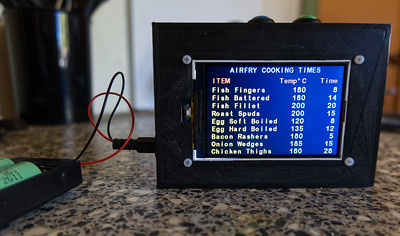
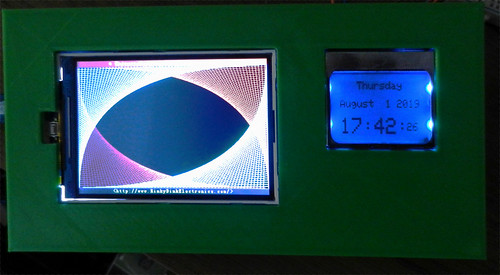
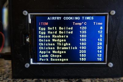
Powered by two lithium rechargeable cells. The green and blue buttons on top allow me to scroll up and down through the list.

IMG_0652

Three days of muttering, reading, rewriting code seems a lot for what ended up as less that 100 lines of code but I learned quite a lot and am finding it a useful addition to the kitchen clutter.

Saturday, 7 March 2020

Stacking Again

First a short demo video showing the unit in operation.


There is a 1.5 second delay between each shot. I had to set it that long as the M5 takes most of that time before it is ready for the next shot.

60 focus stacked shots for this photo of my Venus Fly Trap.

IMG_0907_IMG_0966

I think this rail would have enough room for up to 80 shots.

Friday, 6 March 2020

Focus Stacking Home Brew Setup

A short while ago I was impressed reading a project on Instructables. It sparked the idea of trying something similar but programmed by an Arduino. After a couple of weeks thinking (comes hard some days), programming, buying, 3D printing and constructing I ended up with:

IMG_0144

This consists of the electronics bits

IMG_0140

Left to right: relay to activate camera shutter, stepper motor driver module, Arduino Uno R3 with added extra contacts.

The Arduino is programmed using a home 3D printed panel which uses an LCD to indicate what is happening. Three buttons. Top: set the number of photos to be taken, Middle: start the sequence, Bottom: abort / restart.

 IMG_0139

The camera sits on top of a bought unit which was originally designed to use on the Z axis of a CNC machine. The stepper motor takes 16 moves to forward the camera 10mm. This is set by DIP switches on the driver module. I also added a micro switch as the camera is automatically rewound to the start position once all the macro shots have been taken.

IMG_0142

A few odds and ends were used to make the mount for the camera.

For my first test I mounted the Canon M5 fitted with 18-150mm zoom lens plus the Raynox DCR-150 macro / close-up conversion lens to take 36 focus stacked shots of a small cactus flower.

Why go to all the trouble of taking so many photos?
Getting close to things can result in a very shallow depth of focus on any single shot.
For example

First shot:
IMG_0819

Last shot:
IMG_0854

Each photo in the stack has a slightly different area of the subject in focus.
The two programs I use can sort out the in focus parts and combine just those bits to make the final composite shot.

The result using Zerene Stacker to process the individual photos to make one stacked picture

2020-03-05-17.56.05 ZS 
PMax

I recently purchased Focus Stacker and this is the result from the same batch of 36 photos

IMG_0819_IMG_0854

The main difference in output, to my eyes, is the latter has a better colour rendering.
The unit actually works so I'm a happy bunny.

A bit of extra processing in Affinity Photo

 IMG_0819_IMG_0854af

to increase contrast and vibrance.

Friday, 2 August 2019

RTC done

It took quite a bit of fiddling with the code to get a reasonable layout for the real time clock but I got there in then end. The time is generated in a clock chip which has a back-up battery to keep it going during power outages. One main problem was initially loading the correct time and date. There are plenty of example codes which take the computer time and upload that to the chip. The problem with those is the time taken to compile and upload the instructions. Using that method resulted in a 30 second error. In the end I found one example which allowed the data to be keyboard entered using the serial monitor which is all but instantaneous. The display is a Nokia 5110 as used in their early mobile phones and available almost anywhere on the internet for a few pounds. Though b/w it has blue LED back lights. I will probably add a switch as they are not needed in daylight.

Working clock:

DSCN9902

Just a test pattern program running in the colour display.

I had hoped to add air quality monitoring to the time display but so far that has failed. Tried several example codes but none have worked fully and when I added the code alongside the clock code the time stopped displaying!

Monday, 17 June 2019

Latest Arduino Project

It has been quite a long time since I last had a tinker with an Arduino project. The last one was a weather station with digital readout. That never reached its final stage. All was going well until the day I updated the Arduino IDE (the program used to program an Arduino). The update went badly wrong. It kept reporting errors and wouldn't recognise the instruction I had written previously.

Recently I decided to delete all the old IDE files and install the latest version from scratch. Then a new weather station project on the Instructables site caught my interest. It uses a 3.5 inch full colour TFT display to show the readings in graphical form. The display used is designed to fit on and use with an Arduino Mega. It has a resolution of 480 x 320 pixels.

I found one for sale on eBay direct from China for less than £8 which included postage. After 10 days it arrived. I also had to purchase the tiny unit which actually measures temperature, air pressure and works out the relative humidity. I already had an Arduino Mega.

The sensor module, sensor is the tiny metal box top right
DSCN9700

As always there were other 'libraries' of instructions to install which enable access to the sensor and TFT display. It took a while to find the TFT library files but I discovered a set on the Rinky-Dink Electronics site. They installed and worked perfectly.

Once the program was installed and tested I made some alterations to the original. As well as the graph the most recent readings are now shown numerically just above the X axis. Also I had to alter the range of values on the Y axis to suit the possible range of local readings. At first I thought the pressure readings seemed to be far too high but checking on the Met Office site showed it to be within 1mbar. More accurate than my commercial weather station!

IMG_0678

The display shows up to 36 hours of data (one new reading every 6 minutes) which makes it possible to see weather trends. The above was taken after a 26 hr test run with the unit in the conservatory. When the screen is full the graphs are scrolled from right to left by one pixel with each new reading. Maybe I will change the timing to every 8 minutes so as to display the trend over 48hrs.

Obviously to be of any use the detector needs to be outdoors in a suitable container. Ideally, once I've finished tinkering, I  will have a go at designing and 3D printing a suitable box to hold the Mega and TFT display.

I am so delighted with the possibilities of this colour display I have ordered another one  to experiment with. Screen refresh is slowish so not suitable for displaying video for example.

Saturday, 19 March 2016

First Extended Time Lapse Experiment

On Thursday afternoon I started a first test run for a long duration time lapse video. As I was checking the apples I keep for the Blackbirds I noticed a couple going bad. That gave me the idea of cutting a good one one in half and filming it over several days, one shot every 10 minutes.

That is 6 each hour, 144 photos each day. Each day of shooting producing about 5 seconds of video. The camera card should hold 1,150 photos which may well not be enough, about 8 days worth. I may have to reduce the picture quality a little, buy a larger card or lengthen the time lapse.

The first set up:

DSCN5985

The 12V battery is on the left next to the topless grey box containing the Arduino Nano and associated electronics with a 2 digit display to show how many minutes between shots. It is now programmable from 1 to 60 minutes delay in whole minutes. That switches on three 12V LED lamps for each photo and fires the 350D.

After a short test I decided too much daylight was reaching the subject so I rearranged things with the apple inside an upturned cardboard box which should help keep the lighting from the three 12V LED lamps more even day and night.

 DSCN5992

Only time, a long time, will tell how successful it has been. and whether the battery will last long enough. No problem with the camera as that is powered from a mains adaptor. The lamps are the largest drain on the battery but they are only on for 2 seconds for each photo.

This morning I checked the battery and its voltage had dropped a bit below 11V so the light from the LED lamps had lessened. Fortunately I was able to find a 12V 1A power supply to replace the battery.

Friday, 29 January 2016

New Arduino Project

Today there should have been a nice video of a Blackbird enjoying some apple pieces I had put out but on reviewing the footage today I found the camera had focussed on the background instead of the bird.

Long time readers may remember I built a rain gauge around an Arduino Mega with a digital read out. That has proved to be very reliable so I have decoded to expand on its capabilities. This time instead of using a four line LED display which can only be read from a close distance I intend to rebuild the unit using an Arduino Uno this time and the display will be 10mm tall individual seven segment displays. That has meant learning some new coding to access the display. I bought an eight digit seven segment display which has a MAX7219 chip on board which needs only five wires to access it.

Not only will the display show rainfall but also temperature and humidity. The idea being to use four of the LEDs to show temperature and the other four to show the humidity. Also I have ordered a further two digit seven segment display to show the rainfall.

So far I have got as far as uploading a test routine to make sure I can access all the digits and the decimal points. The latter took me longer to understand the instructions I found on the internet. This is a short video of the test display:


For those who may be interested this is the sketch (program) which is uploaded to the Arduino.
It is my modification of one I found on the internet::

//We always have to include the library
#include "LedControl.h"

/*
 Now we need a LedControl to work with.
 ***** These pin numbers are used on my Uno R3 *****
 pin 12 is connected to the DataIn
 pin 11 is connected to the CLK
 pin 10 is connected to LOAD
 We have only a single MAX72XX.
 */
LedControl lc=LedControl(12,11,10,1);

/* wait a bit between updates of the display */
unsigned long delaytime=350;

void setup() {
  /*
   The MAX72XX is in power-saving mode on startup,
   we have to do a wakeup call
   */
  lc.shutdown(0,false);
  /* Set the brightness to a low value */
  lc.setIntensity(0,2);
  /* and clear the display */
  lc.clearDisplay(0);
}


/*
 This will display the characters for the
 word "Arduino" one after the other.
 */
void writeArduinoOn7Segment() {
  lc.setChar(0,7,'a',false);
  delay(delaytime);
  lc.setRow(0,6,0x05);
  delay(delaytime);
  lc.setChar(0,5,'d',false);
  delay(delaytime);
  lc.setRow(0,4,0x1c);
  delay(delaytime);
  lc.setRow(0,3,B00010000);
  delay(delaytime);
  lc.setRow(0,2,0x15);
  delay(delaytime);
  lc.setRow(0,1,0x1D);
  delay(delaytime);
 // lc.clearDisplay(0);
  delay(delaytime);
}

/*
  This will scroll all the decimal numbers
  and flash the decimal point on LED 0.
 */
void scrollDigits() {
for(int i=0;i<10 br="" i="">    lc.setDigit(0,0,i,false);
    delay(delaytime);
   lc.setDigit(0,0,i,'dp');
   delay(delaytime);
  }
  delay(delaytime);
  lc.clearDisplay(0);
  delay(delaytime);
}

void loop() {
  writeArduinoOn7Segment();
  delay(delaytime);
  scrollDigits();
 
}

Saturday, 20 October 2012

Heath Robinson Meets Arduino

For a while I have wanted a slow rotating platform to film small objects. The one I built at least a year ago had the disadvantage that the stepper motor made large jumps for each step and was only suitable for taking a series of stills which then had to be put together to make a video.

Recently I spotted  some very cheap 5V stepper motors which are often sold complete with the driver board. These motors are small and have a step angle of only 5.625 degrees. That means it will take 64 steps to rotate a full circle. All it needed was wiring to an Arduino Nano (any model of Arduino will work) and loading the sketch (program instructions) which was freely available on the web.

Here is the setup:
Left to right: 5V power regulator  -  driver board  -  Arduino Nano

P1040206c.jpg

Upturned turntable cut from a spare piece of uPVC window ledge showing the stepper motor:

P1040208c.jpg

A hastily rigged up Heath Robinson set up to test whether it was any use for making videos:

P1040205c.jpg

The first results filmed using a Panasonic SDR-H80. The most difficult part was having to use manual focus which is hard to judge on the small LCD screen.


Now it needs tidying up and mounting in a framework.

As for the other project - rain gauge - I've been giving the latest real time clock a 'soak' test and am pleased to see that it seems to be keeping good time. When I programmed it it was 1 second fast (hard to get it exact as you have to guess how long it takes for the program to compile on the computer and download to the Nano) and it is still only 1 second fast.
Related Posts with Thumbnails