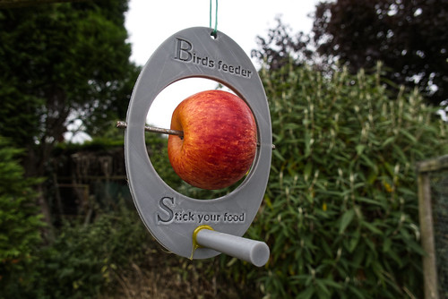
From time to time I have seen some feeders designed to hold an apple for those birds which like them. Here it is the Blackbirds which really go for them when I put some on top of the fruit cage. The, though albeit not too expensive, cost of buying such a feeder has put me off as there is no guarantee the local birds will use one. One day as I was browsing for ideas for 3d printing on Thingiverse I happened on a design for one. It can be seen HERE. All I had to do was download the .stl files and use Ultimate Cura to produce the gcode file for my 3D printer.
It is in three parts. The main body plus two sections of perch. I didn't have any glue suitable for PLA plastics so I used hot melt glue to hold everything in place. I fixed the apple in place by inserting an oval brad nail from each side.
Only time will tell whether the birds will be attracted to it and enjoy a bit of apple. The only reservation I have about the design is the short length of the perches. They seem to be too short for a Blackbird to balance on. I will print some longer perches if need be.
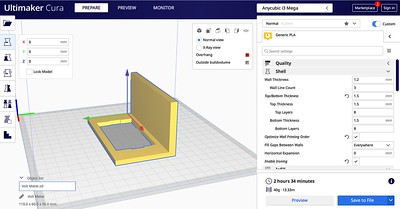
As the power supply for my transmitters resides under the desk I have a separate volt meter so I can check that all is working as it should. My old LED one had some failed LEDs so I bought a cheap LCD one to replace it. The bare unit needed something to hold it in place so after 30 mins in TinkerCad I came up with:
The instruction were copied to Ultimaker Cura to produce a file for the 3D printer.
Unit rotated to print face down. No supports needed that way round.
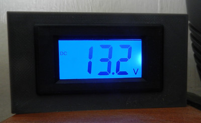
2hr 34 minutes later it was ready to fit the meter:
Had to do a bit of minor filing as the hole was about 0.5mm too small but soon it was mounted, wired up and connected:
Backgrounds for macro shots taken indoors needed to be thought about.
For some subjects I like the idea of a single colour like the green used in my last post.
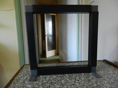
To that end I needed a small frame to which I could attach a coloured A4 sheet.
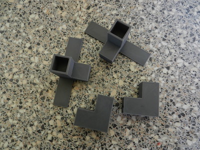
Looking through my goodie (read junk) pile I found some lengths of plastic box section.
As they were originally for a pole to support an LED garden lamp the only joiners were straight.
I needed right angle corner joints and some feet to stop the assembly from falling over.
Just the project for 3D printing.
Parts were designed in FreeCAD
and the designs process using Cura
to write the instructions for my 3D printer.
It took a few experimental prints before the final design worked as anticipated.
Box sections free standing
A couple of clamps hold an A4 sheet in place
I have a range of coloured sheets I bought about 20 years ago.
I might even get to use some of them now.
I can imagine the possibility of using white sheet with the lighting from behind to make macro silhouettes.
It might be possible to use backgrounds printed from old photographs.
Time to experiment.
A problem had arisen with the 3D printer.
The table bed was lifting away from the heater element in one corner.
That was actually causing several problems while printing. The nearer the print head was to that corner the larger the chance of the nozzle scraping on the bed. Also without a small gap between the nozzle and the bed no material was being laid down. Lastly it also meant there would be significant changes in temperature across the bed which doesn't help with initial adhesion of the PLA. It wasn't really noticeable until I started printing the front panel for my weather displays. That used nearly the full width of the bed. This problem is not unknown and a 'temporary' fix was easily implemented. Measure the thickness of the bed and heater plate when they were properly touching and design a clamp to hold them in place. That is just what I did in Tinkercad:
Then I printed out four of them in case they were needed on all four corners of the bed.
As it happened I only needed to use two. Fitting one at the front left
caused the diagonally opposite corner to lift slightly so I put one there as well.
Job done and the next print session showed the problem was cured, for now anyway.
You may be thinking that the heat from the bed would cause the clamps to melt, or at least warp. Not so as the temperature used to melt the PLA in the nozzle is over 100 degrees hotter than the bed temperature.
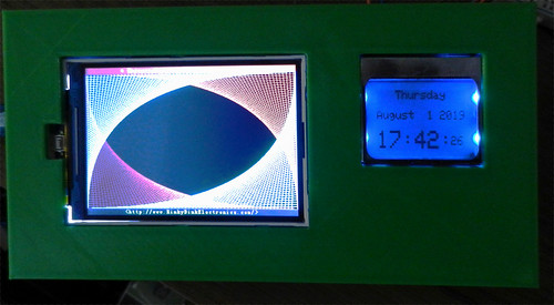
It took quite a bit of fiddling with the code to get a reasonable layout for the real time clock but I got there in then end. The time is generated in a clock chip which has a back-up battery to keep it going during power outages. One main problem was initially loading the correct time and date. There are plenty of example codes which take the computer time and upload that to the chip. The problem with those is the time taken to compile and upload the instructions. Using that method resulted in a 30 second error. In the end I found one example which allowed the data to be keyboard entered using the serial monitor which is all but instantaneous. The display is a Nokia 5110 as used in their early mobile phones and available almost anywhere on the internet for a few pounds. Though b/w it has blue LED back lights. I will probably add a switch as they are not needed in daylight.
Working clock:
Just a test pattern program running in the colour display.
I had hoped to add air quality monitoring to the time display but so far that has failed. Tried several example codes but none have worked fully and when I added the code alongside the clock code the time stopped displaying!
The colour screen is moved to the left.
Space above and below reset button now covered over.
b/w screen added on the right.
The aim being for the colour screen to show a weather forecast picked up from the internet.
The small screen to show a real time clock and maybe the air quality display.
My thinking at the moment is to use an Arduino Uno or Mini for the b/w display and an Arduino Mega to connect to the internet and display the information received graphically on the colour screen.
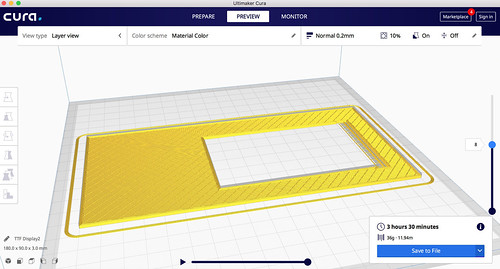
It was about time I put the 3D printer back into use. I have an idea for a different way to display weather information, including air quality, using the 3.5 inch TFT colour display connected to an Arduino Mega. To that end I have started designing a front panel for an enclosure for all the gubbins.
Measured the size of the actual display panel and used TinkerCad to start designing a 3mm thick panel.
Saved the instructions as a .stl file which was loaded into ultimate Cura to make the instructions the
3D printer needs
This is actually mk2. With the original simple cut out (which amazingly fitted first time) there was a slight problem. The right hand side of the display circuit board has many pins for the connections. They stopped the display from being perfectly flat. As might just be discernible on the above picture there is now a cut out section 1.5mm deep to take care of this.
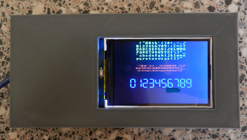
Photo of mk1 prototype with screen fitted (just showing a font test program)
Another section which will probably have a bit of work done is on the left hand side. There is a reset button on the circuit board so I will have to redesign the filled area to fit round this. It's a slow old job as each 3D test print takes about 3.5 hours to complete.
Marks on the screen are from the protective clear plastic covering which I have left in place.
I decided to 3D print a name sign for my home.
It is taking a few trial test prints to check my CAD efforts are producing what I need.
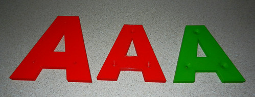
The sign will be made with seven individual letters.
Just working on the first letter at the moment.
I started with a letter height of 120mm with three holes for screws.
That was bigger than needed really and took about 5 hours to print.
For a second test print I reduced the height to 100mm - much better.
Also at Adrian's suggestion I tried to make countersunk holes (middle red letter A)
Unfortunately I didn't get them centred over the holes and the slope was too sharp.
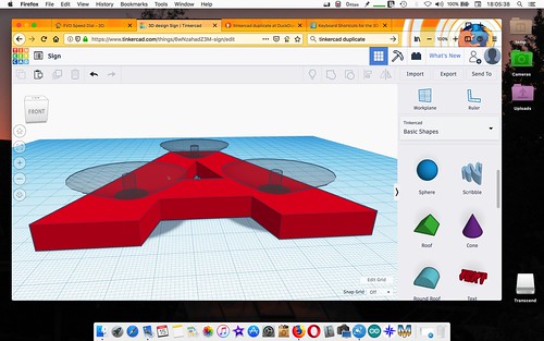
Back to TinkerCAD to try again.
The holes are made with thin cylinders.
The countersinking made with inverted cones and nicely aligned after much jiggling.
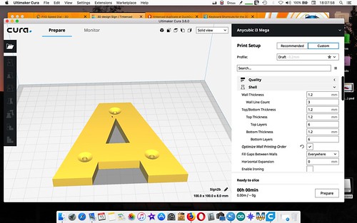
Saved and the file loaded in Cura
Reduced the infill to 8% and speeded up the extruder moves.
That brought the time down to 2h 45m
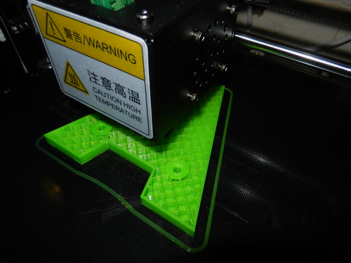
That print (in green above) looked much better.
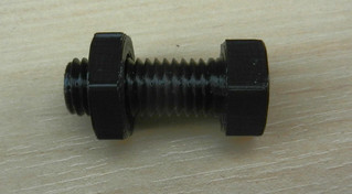
Last week I was experimenting with printing 3D nuts and bolts / screws.
FreeCAD includes data for many standard sizes.
This is a 12mm screw + nut:
What I found was when printing a 12mm screw and then the corresponding 12mm nut, the nut was slightly too small and wouldn't fit. In the end I had to increase the size of the nut in the X and Y directions by about 10% in Cura to produce one which fits.
This week I have had a look at TinkerCAD. This is an on line 3D modelling site run by Autodesk.
Free to join up and experiment with. One can start with basic 3D solid shapes and 'tinker' with them to produce whatever your imagination can come up with. An ideal site for beginners to CAD (computer aided design), such as myself.
Once I had gone through all the basic tutorials what to build as a first project?
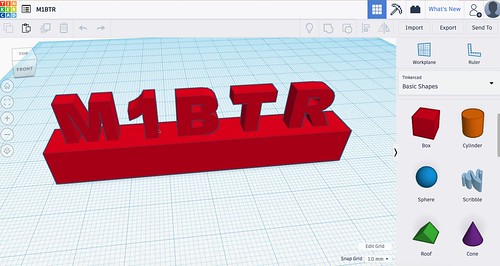
A small free standing sign with my amateur radio callsign came to mind.
The base is made from a basic cube, stretched and resized.
Fortunately a block letter alphabet is included in the choice of 3D shapes.
These were added singly, rotated and moved to fit on top of the base block.
There are very easy, once learned, facilities for aligning the various parts.
Once designing was finished the project was saved to the laptop as a .stl file.
Then loaded in Cura to produce the instructions for the 3D printer.
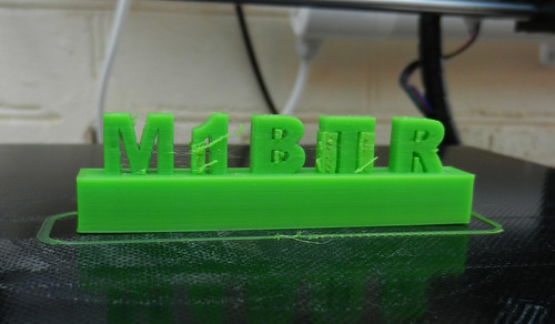
Temporary thin supports had to be included in the instructions for sections of the design which would be created overhanging the base level.
Resulting 3D print:
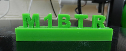
Once the temporary supports had been removed:
The base may look as though it is a solid lump but it is mainly hollow with a 20% infill of criss cross supports. Total print time 1hr 9min..
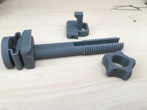
I have been searching through many designs for 3D printed holders for phones which were suitable for use on a tripod. Finally I found one on thingiverse I thought worth trying out.
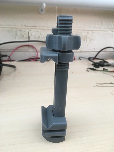
Just three printed sections
which fit together to make
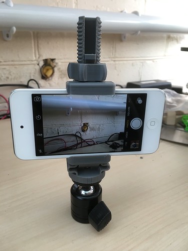
I fitted it to a universal ball joint I already had and clamped my iPod
The whole thing will fit on the standard screw on a tripod.
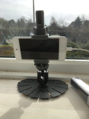
I also found the stand from an old 7 inch monitor and attached it to that
so I could stand and angle it in the bedroom window to take a time lapse video.
The block on the right is a rechargeable 5V power bank.
Useful when something may need power for an extended period.
Not a brilliant day for time lapse photography!
If I understood things correctly the built in Apple Camera app (when set to the time lapse setting) chooses the number of frames per second so that the resulting video is no more than 40 seconds long no matter how long it has been filming. It does this after the recording has been stopped. Not exactly a speedy process but nor is it speedy transferring 100s of individual photos to a laptop and putting them together to make a video,
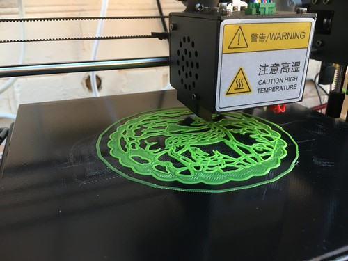
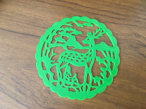
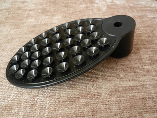
I just had to make this 3D printable decoration found on the Thingiverse web site.
Designed by user hyojung0320
Being printed with green PLA:
Finished item:
Print time just under an hour.
Size about 11cm (4.25in) across and 1.5mm thick.
I chose this as a trial in printing something with reasonable detail.
On close examination there are some tiny gaps in the structure.
Maybe if I had chosen a finer print setting it would have been better through that would have taken a bit over 2 hours to print.
I must get some more colours. Not cheap but each 1kg reel seems to last a long while.
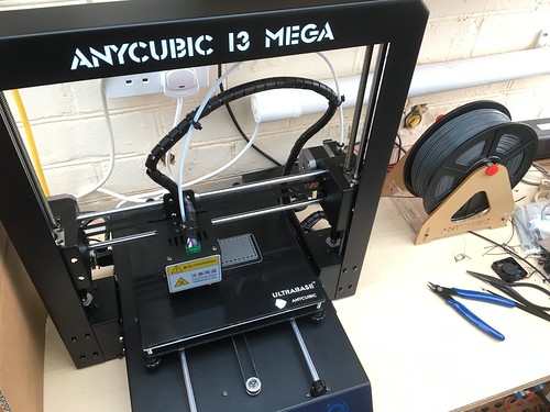
It's been too darned cold in the unheated conservatory to consider 3D printing until today.
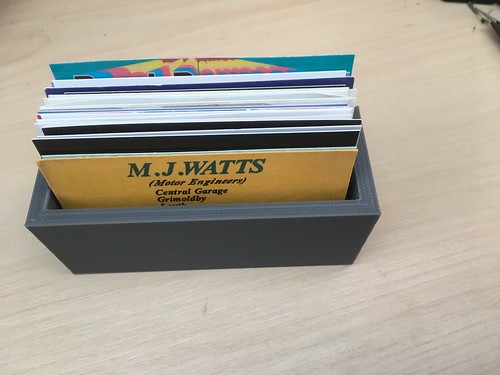
I have a small collection of business cards which usually end up in an untidy pile on the desk.
Then I keep knocking and scattering them on the floor.
I had been looking for a simple idea for my first 'from scratch' 3D design.
Previously I had only used designs downloaded from various sites.
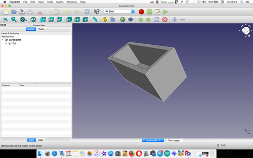
A little box to keep the cards tidy seemed like a good place to start.
First task was to come to terms with v0.18 of FreeCAD to design the box.
Essentially it is made starting with two solid cubes.
One is enlarged to make the outside walls of the box.
The second is made slightly smaller to make the inside walls.
The small one is fitted inside the larger one and the program told to cut out the smaller one.
This makes the hollow box to hold the cards.
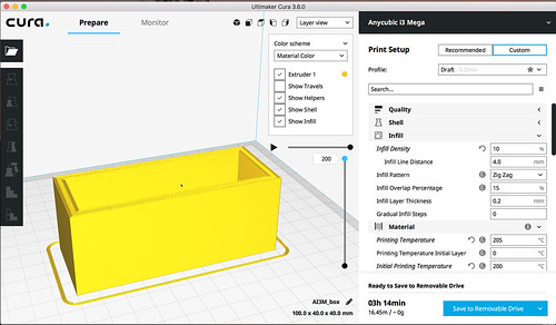
The idea was to save that as a .stl file for the next process but FreeCAD refused to do that.
Fortunately there are lots of export choices so I tried saving it as a .obj file.
That worked.
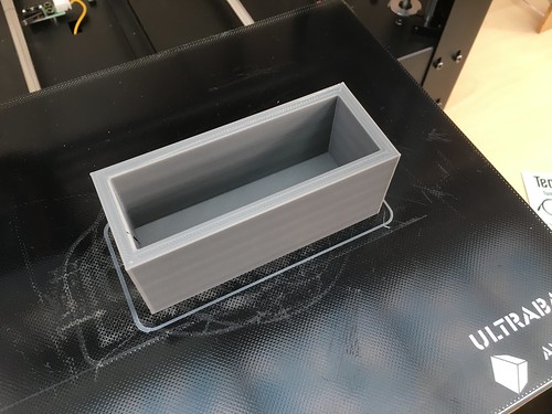
Next I loaded the .obj file in Ultimaker Cura and told it to slice the design to make the instructions needed by the 3D printer. It will instruct the printer what to do on each 0.2mm layer.
That was saved as a .gcode file and transferred to the 3D printer on an SD card.
Reel of grey PLA filament loaded.
Finally the long wait as the printer strutted its stuff to create the box.
a partly universal fitting to add a phone (camera) to the microscope.
It was to replace the one which came with the microscope
Whilst being very adaptable as far a suiting a vast range of cameras I was never happy with the idea of suction cups as a method of holding it in place. I did once have my iPod slide off.
Unfortunately the replacement design I had downloaded and printed out was
a) fragile - I snapped one bit trying to fit it together.
b) it didn't suit the iPhone 6s with its corner positioned camera.
probably fine with phones with a camera nearer half way across their body.
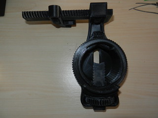
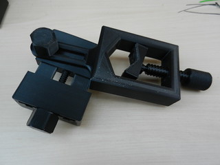
I had a look round on the Thingiverse site and found another design which looked a better bet.
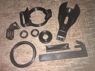
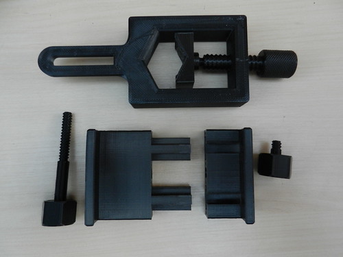
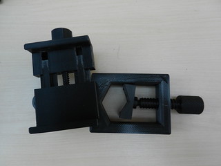
Here are the parts once printed out
I had already fitted together the three parts which make up the bit at the top of the photo.
On the V shaped section there is a ball and socket joint in which the end of the screw fits. This is three sections around the ball. One of those snapped as it was too close a fit but everything still holds in place.
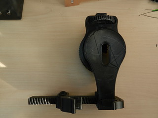
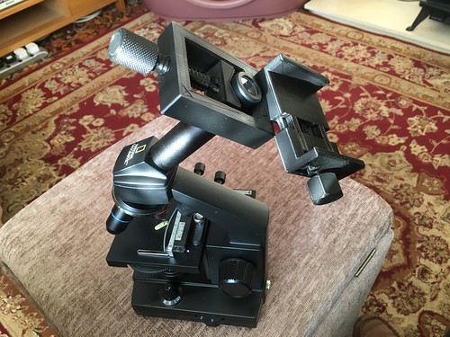
All the parts assembled
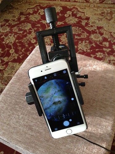
Fitted to the microscope
With camera firmly held in place
Fortunately my phone has an added cover over the back and sides which protects the volume and power buttons or the clamp would press and activate them. I think I will add some of the old style adhesive foam strip we used to use for sealing gaps in wooden window frames years ago. That should cushion any possible pressure on the phone's buttons.
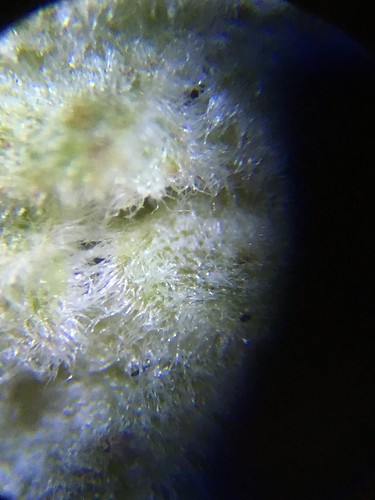
A photo of the hazel catkin with this set up
I did have problems with keeping the items stuck on the printer bed to start with. I think it was the overall low temperature in the unheated conservatory. Things were cooling down too fast. Increased the bed temperature from the usual 60C to 63C and the extruding temperature from the usual 200C to 205C and all worked perfectly.
A short video of the printer at work
I toned down the sound. The printer has four cooling fans and four stepper motors which can be noisyish at times.
My grateful thanks to user 'falconphysics' for publishing the design on Thingiverse.